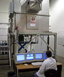
Equipment Testing Chamber ATC-12
Amtech supplies Aerosol Chambers for test and evaluation purposes in several configurations, complete with specialist and surge support for training, operation, maintenance and upgrades. Our commercially available 12 cubic-metre Aerosol Chamber (ATC-12) comes complete with referee and control systems and software.
Capable of static and dynamic cloud generation, it is used in-house by Amtech as well as defense research institutes and defense contractors in Europe and North America to replicate real-world simulation exercises for systems under test, and for development and refinement of collection and detection systems.
Test instruments, rather than being placed inside the chamber, are placed below the chamber, with only the air intake of each instrument being introduced into the chamber. This is useful for allowing manipulation of test equipment, setup and operation of the disseminators, changing agar plates on slit samplers, and for replenishing liquid on test items such as the XMX liquid collector without breaching the fidelity of chamber seal.
Secondly, an airlock and glove box style access are used, to allow the operator to move items in and out of the aerosol chamber or to maneuver items inside the chamber again without breaching the chamber seal. This is particularly useful for test setup and preparation as well as for adding new or additional test solutions to the disseminators – the chamber can be left in a state of readiness and does not have to be evacuated and/or decontaminated between tests.
Aerosol Chamber Mechanical
- The chamber is built of 14-gauge stainless steel.
- Approximate size is 3m long x 2m wide x 2m high for a total volume of 12m3, it is manufactured in two sections (a top half and a bottom half) to allow for simplified shipping and assembly on-site. Each half is 3m long x 2m wide x 1m high.
- Manufactured with two observation windows, one maintenance access door, one door for the aerosol generator access, an airlock for material/supply transfer, and three glove box style inlets for working in the chamber while it is pressurized.
- Four instrument-sampling ports are available through the bottom of the chamber; three additional sampling ports are used for referee and control system instrumentation; instruments will be positioned underneath the chamber, with their intakes protruding through the sampling port into the chamber.
- Two recirculating fans will provide for airflow and maintaining particle suspension and homogeneous mixing during a test.
HVAC System
The HVAC system is a simple open-loop design. Air is drawn through a HEPA filter into the chamber from the room or ducted in from the building exterior and exhausted from the chamber through a second HEPA filter, again in to the room or ducted outside. Prefilters are included before both HEPAs to lengthen the life of the more expensive filters.
Furthermore, hoses and HEPA filters are provided to cleanse any air drawn out from the chamber and exhausted at the output of any sampling hardware or equipment under test.
Temperature and Humidity
The chamber continually monitors and logs the temperature and humidity inside the chamber but does not provide any control over these variables. If venting from the room, temperatures at or slightly above room temperature can be expected, while venting to and from the building exterior will result in external ambient air temperatures inside the chamber.
Negative Pressure System
The internal chamber pressure is also continually monitored and logged. A duct fan, positioned after the exhaust HEPA filter is used to regulate the airflow through the chamber and provide a negative pressure differential. Thus, any break in the chamber seal would cause an inflow of air into the chamber and prevent any release into the surrounding room.
Control System and Chamber Electrical
Through the Chamber Control System, the user has the ability to monitor and manipulate virtually every component of the system. The chamber control system will manage all aspects of the aerosol chamber operation and also interfaces with the HVAC and Referee systems to coordinate their operation. This subsystem consists of the chamber control software, and all required electrical hardware and associated materials.
The control system provides the user with the ability to control and/or monitor various aspects of the chamber operation.
Aerosol Chamber Control Software
The system control computer runs the chamber control software, which provides the graphical user interface for the operator. It is used to display real time and historical trend control and sensor data, and stores all historical data for later extraction; the computer includes four monitors for display of important real-time and historical control data. A network hub for connection of additional computers is also included.
Referee System
The chamber referee system includes the hardware and software module used to actuate and control the dissemination of aerosols, the measurement and sampling equipment, as well as the decontamination process. This system allows for the generation and subsequent measurement of both benign background aerosols and active biological simulant aerosols.
Aerosol Cloud Generation
The referee system software module integrates directly into the chamber control software and allows the user to program controlled aerosol releases. The system allows the user to generate a background interferent cloud of stable concentration using one disseminator while generating a stable or dynamic biological simulant aerosol with the other disseminator.
The aerosol cloud generator also allows the user to develop consistently repeatable static or dynamic agent simulant aerosol clouds.
All four types of commonly used biological agent simulants have been tested for use in the chamber. Bacillus globigii, erwinia herbicola, MS2, and ovalbumin and used to simulant bacterial spores, vegetative bacteria, viruses, and biological toxins, respectively. Consistent releases down to a minimum of 10 ACPLA, are achievable using the aerosol cloud generator.
Disseminators
Aerosol dissemination is accomplished using simple and inexpensive medical style nebulizers. Two independent disseminator connections are supplied to provide the ability to use alternate aerosolizing devices or to spray more than one substance simultaneously. The PID controller actuates one of the connections while the custom cloud generator can be used to control the other connection.
Aerosol Sampling
The chamber floor provides 7 seven sampling ports to be used for both equipment under test and the referee sampling hardware. Two slit-to-agar air samplers are typically used with this system and are mounted on opposite sides of the chamber. The slit samplers also have the capability to interface to Amtech chamber control software, providing device flow rate feedback and remote trigger starting ability.
A particle counter or an Aerodynamic Particle Sizer (APS) is also used and generally installed at the center sampling port in the chamber. This device is used to provide an aerosol concentration measurement within the test chamber.
Decontamination
The aerosol test chamber decontamination can be accomplished with UV irradiation or manual bleaching. The UV process is intended for daily (or more frequent) use while the manual bleach process is generally used to provide a complete scrub down of all surfaces (especially those shadowed from the light or hidden from the airflow) with a much lower frequency.
Specifications
Requirement |
Specification |
|
| Humidity | Low | No control; Operational within 10 – 90% RH |
| High | ||
| Humidity Control | Accuracy | Measurement: ±5% |
| Temperature | High | No control; Operational within 10 – 35°C |
| Low | ||
| Temperature Control | Accuracy | Measurement: ±2°C |
| Ambient Air Temperature | Range | +10°C to +35°C with no temperature regulation |
| Static Aerosol Generation | Low | ±50% @ 10 ACPLA (BG) |
| High | ±15% @ 1,000 ACPLA (BG) | |
| Decontamination | UV Irradiation or Bleach | |
| Pressure Control | Typical | 50 – 150Pa neg. differential |
| Filtration System | HEPA with prefilters | |
| Dimensions – Internal Test Chamber | Width | 2m |
| Length |
3m |
|
| Height | 2m | |
| Volume | 12m3 | |
| Dimensions – External | Width | ~3m |
| Length | ~6m | |
| Height | ~4m | |
| Material | Interior | Stainless Steel |
| Exterior | Stainless Steel | |
| HVAC | N/A | |
| Airlock Entry | Custom Airlock Flange | |
| Test Chamber Doors | 0.7m x 0.7m access door | |
| Test Chamber Windows | Two observation windows and airlock porthole | |
| Electrical Compliance | CSA/UL | |